Rigid-Body Image Registration using Tiepoints: An Error Minimization Technique
D. Rose - May, 2024
Abstract
This paper describes a method of registering one image to another, where the degrees of freedom include only translation, rotation, and scale. This method uses a set of two or more tiepoint pairs1 (a list of (x,y) coordinates in the first image, and their corresponding (x,y) locations in the second image), which may be derived manually or through some automated correlation process. The method uses a closed-form error minimization technique to find a best-fit global solution. As far as the author is aware, this is an original technique.
Introduction
In the realm of image processing, it is occasionally useful to register two images together. That is, we wish to develop a mathematical equation that maps any (x,y) coordinate in one image to its corresponding coordinate in a second image. Having derived such an equation, we can then resample one of the images so that it aligns with the other.
For this paper, we limit ourselves to a “rigid body” transform: that is, we will only allow the transformed image to be translated, rotated and scaled in order to bring it into alignment with the second image. There are a number of equation forms commonly used for image registration, such as the projective transform and the affine transform, both of which can model translation, rotation and scale, as well as other degrees of freedom. However, if we have a priori knowledge that only translation, rotation and scale are necessary, limiting the degrees of freedom to only those parameters will generally result in a more accurate solution.
Examples of where a rigid-body solution may be appropriate include:
- Example 1: We would like to scan a piece of art, such as a medieval manuscript or oil painting using a flat-bed scanner, but the artwork is too large to scan all at once. We therefore scan the artwork in overlapping sections, and register them back together into one continuous image using the methods described herein.
- Example 2: We would like to register a ground-plane Synthetic Aperture Radar (SAR) image or an orthorectified aerial photograph to an existing map, as shown in Figure 1.

Figure 1: Two images that differ in translation, rotation and scale. Tiepoint pairs are selected to link locations in Image A to their counterparts in Image B.
Approach
The solution consists of the following three primary steps.
Step 1: Compute the centroid (geometric center) of the tiepoints in each of the two images. These two points become the centers of rotation for our transform2. That is, if we shift the two images so that the centroid of the tiepoints in image A aligns with the centroid of the tiepoints in image B, we need only rotate and scale one of the images around that common point to obtain our solution.
Step 2: Determine the optimal rotation angle required to align the two images. Our approach is based on treating each tiepoint as a vector with origin at the common centroid, and calculating the rotation angle that maximizes the sum of the dot products between tiepoint vector pairs.
Step 3: Determine the global scale factor required to bring the two images into alignment.
Derivation
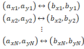
We start with a set of at least two tiepoint pairs between image A and image B, as illustrated in Figure 1:

where (axn, ayn) is a pixel coordinate in image A, (bxn, byn) is the corresponding location in image B, and N is the total number of tiepoint pairs. Our goal is to find an equation that maps any arbitrary point in image A to its corresponding point in image B. For now, we will restrict the degrees of freedom of the solution to only translation and rotation, leaving scale for later. The equation therefore has the following form:


where:
- (ax, ay) is an arbitrary coordinate in image A
- (bx, by) is the corresponding point in Image B
- θ, c and d are the unknown rotation angle and offset parameters that we must solve for.
Calculating the Centroids:
As a first step, we find the geometric center, or centroid of each tiepoint constellation. We do this by calculating the mean value of the x and y coordinates of the tiepoints in each image:


where:
- (max, may) is the centroid of the tiepoints in image A
- (mbx, mby) is the centroid of the tiepoints in image B
The coordinates (max,may) and (mbx,mby) become the centers of rotation for our image transform. We now modify our list of tiepoint pairs by shifting the origins to these centers of rotation:


The new set of shifted tiepoint pairs is therefore:

and the equation we need to solve is reduced to one of pure rotation, as in equation 4:


where the only unknown is the rotation angle θ.
Calculating the Rotation Angle:
The problem now is to find θ that optimizes the fit over our list of shifted tiepoints, where θ is the amount by which image B is rotated with respect to image A, and is positive counter-clockwise. For this, we use the dot product rule:

Note that the dot product of two vectors is a maximum when the angle between them is zero, as shown in Figure 2:

Figure 2: Dot product of two vectors is a maximum when the angle between them is zero
We therefore define a quality metric as the sum of the dot products from each tiepoint pair. Our strategy is to rotate image A around the common centroid until the sum of the dot products between each A and B tiepoint pair reaches a maximum.
Note that since we are minimizing the angles between tiepoint vectors, this result is independent of scale differences between the images.
Combining the rotation equation (equations 4a and 4b) with the dot product equation (equation 5), we have:

where q is the quantity we want to maximize. With some algebraic manipulation we have:

To find the maximum q, we take the derivative with respect to θ, set it to zero, and solve for θ:


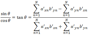
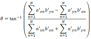
and finally:

The astute reader will have noticed that the dot product function shown in Figure 2 has both a minimum and a maximum, located 180 degrees apart. Both of these are found by setting the derivative to zero, since the arctangent function is ambiguous over a full circle. Fortunately, most programming languages include an atan2() function which resolves this ambiguity. Equation 6 will always produce the correct angle, regardless of how far image B is rotated with respect to image A:

(Note: for most programming languages, the order of arguments for the ATAN2 function is atan2(y,x), as shown above. However, for a few—notably Microsoft Excel— the order of arguments is in the reverse order of atan2(x,y).)
Now that we have the rotation angle and the centers of rotation, we can write out the full transform equation (excluding scale) using the original unshifted tiepoints:


Calculating the Scale:
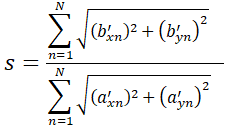
To account for scale, we need to calculate the scale factor. To do this, we compute the sum of the magnitudes of the shifted tiepoint vectors from image A, and again for image B, and take their ratio:

where:
- (a'xn, a'yn) are the tiepoints from image A, relative to the center of rotation in image A
- (b'xn, b'yn) are the tiepoints from image B, relative to the center of rotation in image B
- S is the scale factor
Adding scale to equation 7, we have:

And again after some algebraic manipulation, we have the final solution:


where:
- (max, may) is the centroid of the tiepoints in Image A from equations 2a and 2b
- (mbx, mby) is the centroid of the tiepoints in Image B from equations 2c and 2d
- θ is the rotation angle from equation 6
- S is the scale factor from equation 8
- (ax, ay) is any arbitrary point in Image A
- (bx, by) is the point corresponding to (ax, ay) in Image B
Equation 9 allows us to map any point in image A to its corresponding location in image B. Note that the right half of each equation (inside the parenthesis) are constants, and only need to be computed once. Also, if there happens to be a priori information about any of the parameters—for example, if you already know the rotation angle or scale factor—you can plug them in directly and skip the corresponding computation.
The Inverse Mapping:
The above derivation maps any arbitrary point in Image A to its corresponding location in Image B. If you want to map from a point in B back to A, you have three options:
- Repeat all the above calculations, swapping which image is A and B, or:
- Take the negative of the rotation angle (θ); the inverse of the scale (S); and swap the values for the centroids of image A and B, or:
- Use the general equation for inverting an affine transform as shown below:
Given the general affine transform (where the k values are all constants):

The inverse affine transform is:

Note that the denominator is the same for all terms.
Footnotes (clarifications in response to reader comments):
- In theory, only two tiepoint pairs are required to solve for rigid body registration (rotation, translation, and scale). However, most methods for selecting tiepoints have the potential to introduce slight errors. These errors are likely to be normally distributed in pixel space, with a standard deviation of a pixel or two. The registration method presented above provides a best-fit global solution across an arbitrarily large number of tieponts, in order to minimize the impact of individual tiepoint errors. Note however that the technique will also work if only two tiepoint pairs are provided.
- The only requirement for choosing the center of rotation is that it be located at a point where the two images are known to align. Thus in principle we could use any one of the original tiepoint pairs as the rotation center (as long as we were consistent in calculating the subsequent shifts). However, using the two centroids as the center of rotation will tend to cancel out errors from individual tiepoints, providing a more accurate estimate of a true point of correspondence between images.
Comments and error reports may be sent to the following address. We may post comments of general interest. Be sure to identify the page you are commenting on.
 .
.